
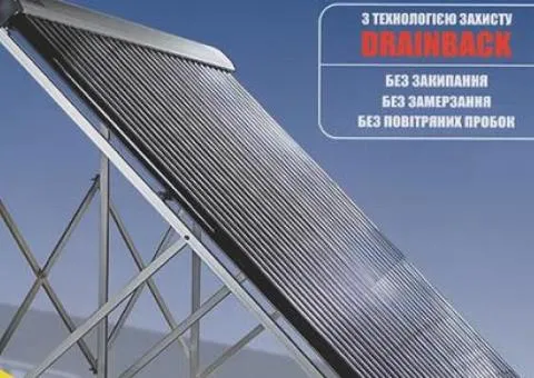
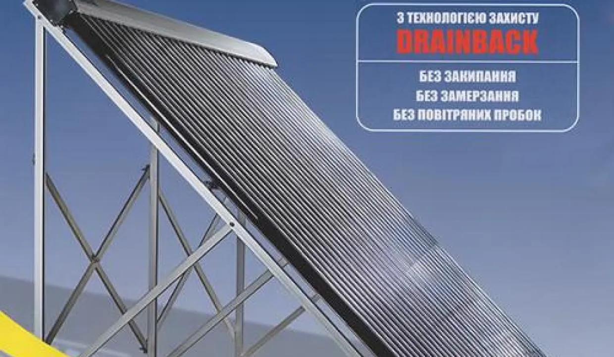
Vacuum solar collector Altek SC-HD-30 DRAINBACK
49,196 ₴
Published 4 days ago by Solar-Tech
49,196 ₴
In Other category
вул. Стеценка, 14/44, Київ, Україна
Get directions →
27 item views
Drainback heliosystem protection technology
The drainback technology is designed to protect the heliosystem from boiling or freezing of the heat transfer fluid and from formation of airlocks. Overheating and presence of air in the system are the main causes of failures that can lead to serious damage. The system consists of special solar collectors, a special tank for draining the heat transfer fluid, a pump group and a storage water heater with a built-in heat exchanger.
Principle of operation of the drainback system
Before operation the solar collectors are filled with air, and all the heat transfer fluid is below their level in the pipelines, the heat exchanger and the special reservoir (drainback tank).
When the temperature in the solar collector rises to the set value, the pump switches on, the heat transfer fluid fills the collectors (displacing the air), absorbs heat and flows to the heat exchanger where it gives off heat to the water. When operation ends, the pump switches off and the heat transfer fluid drains from the collectors, which are again filled with air.
The main advantage of such a system is the ability to protect propylene glycol-based heat transfer fluid from exposure to high temperatures (which reach 200 ˚C and above). Because of this protection principle the DRAINBACK SYSTEM can be called "self-draining." Mainly, this technology is used for small heliosystems with one circulation circuit and one group of solar collectors.
Requirements for the system:
-
The need to use more powerful circulation pumps than usual;
-
The need for periodic complete replacement of glycol-based heat transfer fluid, since the constant presence of air in the system leads to oxidation of the liquid with formation of solid deposits;
-
The heliosystem must not have check valves, an air vent or expansion tanks;
-
Connecting multiple collectors in rows is possible only in parallel using a "Tichtelmann loop"
-
The amount of heat transfer fluid in the system must take into account that a sufficient amount of heat transfer fluid must always remain in the drainback tank.
Features:
-
Connection nozzles are located on the rear panel of the housing to allow draining of the heat transfer fluid.
-
Can be installed on flat and pitched roofs.
-
If a standard pump with a head of 6-7 m.w.c. is used in the system, the height difference between the highest and lowest points of the system should not exceed 6 m.
-
Ideal system option for temporary-use facilities (dachas, country houses);
-
The initial investment amount is lower due to a smaller number of system components;
-
Possible use of water as the heat transfer fluid;
-
During prolonged absence of heat draw-off the heat transfer fluid does not overheat;
-
Back-cooling of the boiler through natural circulation is excluded.
Specifications of the vacuum collector Altek SC-HD-20:
Tube type
Heat pipe (AlN/AlN-SS/Cu)
Number of tubes
30
Collector area, (m2)
4.51
Vacuum tube size, (mm)
58х1800
Condenser diameter, (mm)
14
Condenser length, (mm)
-
Absorber area, (m2)
2.42
Aperture area, m²
1.88
Recommended tank capacity (l)
275 - 325
Maximum heating temperature, (°C)
250
Rated operating temperature, (°C)
-20+90
Maximum operating temperature, (°C)
100
Efficiency, n
0.744
Frame and collector
aluminum alloy
Heat exchanger material
copper
Insulation material
mineral wool 37 mm
Thermistor sleeve, mm
ф8*100
Maximum working pressure, (MPa)
0.6
Recommended flow, l/min* m2
-
Vacuum tube holders
Latch with additional fixation
Installation type
Flat, pitched, vertical surfaces (inclination angle 15-60º)
Metal thickness
-
Dimensions HxWxD, (mm)
-
Weight, (kg)
-
Service life
not less than 15 years
Read morePublished on 2026/10/11
Description
Drainback heliosystem protection technology
The drainback technology is designed to protect the heliosystem from boiling or freezing of the heat transfer fluid and from formation of airlocks. Overheating and presence of air in the system are the main causes of failures that can lead to serious damage. The system consists of special solar collectors, a special tank for draining the heat transfer fluid, a pump group and a storage water heater with a built-in heat exchanger.
Principle of operation of the drainback system
Before operation the solar collectors are filled with air, and all the heat transfer fluid is below their level in the pipelines, the heat exchanger and the special reservoir (drainback tank).
When the temperature in the solar collector rises to the set value, the pump switches on, the heat transfer fluid fills the collectors (displacing the air), absorbs heat and flows to the heat exchanger where it gives off heat to the water. When operation ends, the pump switches off and the heat transfer fluid drains from the collectors, which are again filled with air.
The main advantage of such a system is the ability to protect propylene glycol-based heat transfer fluid from exposure to high temperatures (which reach 200 ˚C and above). Because of this protection principle the DRAINBACK SYSTEM can be called "self-draining." Mainly, this technology is used for small heliosystems with one circulation circuit and one group of solar collectors.
Requirements for the system:
-
The need to use more powerful circulation pumps than usual;
-
The need for periodic complete replacement of glycol-based heat transfer fluid, since the constant presence of air in the system leads to oxidation of the liquid with formation of solid deposits;
-
The heliosystem must not have check valves, an air vent or expansion tanks;
-
Connecting multiple collectors in rows is possible only in parallel using a "Tichtelmann loop"
-
The amount of heat transfer fluid in the system must take into account that a sufficient amount of heat transfer fluid must always remain in the drainback tank.
Features:
-
Connection nozzles are located on the rear panel of the housing to allow draining of the heat transfer fluid.
-
Can be installed on flat and pitched roofs.
-
If a standard pump with a head of 6-7 m.w.c. is used in the system, the height difference between the highest and lowest points of the system should not exceed 6 m.
-
Ideal system option for temporary-use facilities (dachas, country houses);
-
The initial investment amount is lower due to a smaller number of system components;
-
Possible use of water as the heat transfer fluid;
-
During prolonged absence of heat draw-off the heat transfer fluid does not overheat;
-
Back-cooling of the boiler through natural circulation is excluded.
Specifications of the vacuum collector Altek SC-HD-20:
Tube type
Heat pipe (AlN/AlN-SS/Cu)
Number of tubes
30
Collector area, (m2)
4.51
Vacuum tube size, (mm)
58х1800
Condenser diameter, (mm)
14
Condenser length, (mm)
-
Absorber area, (m2)
2.42
Aperture area, m²
1.88
Recommended tank capacity (l)
275 - 325
Maximum heating temperature, (°C)
250
Rated operating temperature, (°C)
-20+90
Maximum operating temperature, (°C)
100
Efficiency, n
0.744
Frame and collector
aluminum alloy
Heat exchanger material
copper
Insulation material
mineral wool 37 mm
Thermistor sleeve, mm
ф8*100
Maximum working pressure, (MPa)
0.6
Recommended flow, l/min* m2
-
Vacuum tube holders
Latch with additional fixation
Installation type
Flat, pitched, vertical surfaces (inclination angle 15-60º)
Metal thickness
-
Dimensions HxWxD, (mm)
-
Weight, (kg)
-
Service life
not less than 15 years
Attributes
Related listings in your area
How far is it?
Show listings in my area
Show only listings that are
km distanced
Show listings
Contact the seller
 User is offline
- 538 active listings
- Company
- Registered for Sunday
- Київ, Київська область, Україна
Related items
 Олег Кокоткін
Today 05:32
Олег Кокоткін
Today 05:32

Verified user
Selling diapers.
20 ₴
Selling diapers.
Житомир, Україна
Adult diapers for sale. Size - M. There are twenty pieces. Twenty hryvnias each. Wholesale, will give for three hundred hryvnias. Also, there are diaper-pants, in the quantity of seven pieces. German. Size - XL. Two hundred hryvnias for all.
Today
Colour: White
State: New
Other
10028 - В ільський шлях
20 ₴
Олег Кокоткін
Tuesday 10:45
Verified user
Glass jars for sale
5 ₴
Glass jars for sale
Житомир, Україна
Glass jars for sale. Used. In good condition. Nonstandard round ones of 485 grams - 58 pieces. 5 hryvnias each. Nonstandard tall ones of 485 grams - 15 pieces. 5 hryvnias each. Nonstandard of various volumes - 16 pieces. Negotiable. Small jars of 190 grams - 30 pieces. 2 hryvnias each. No standard half-liter jars. One-liter jars eight pieces. 100 hryvnias.
Tuesday
Material: Стекло
State: Used
Other
10028 - В ільський шлях
5 ₴
 Solar-Tech
Sunday 11:56
Solar-Tech
Sunday 11:56
Hot water storage tank made of black steel TEPLOBAK VTA-1-2000 (upper heat exchanger 6.90 sq. m.)
156,013 ₴
Hot water storage tank made of black steel TEPLOBAK VTA-1-2000 (upper heat exchanger 6.90 sq. m.)
Київ, Україна
Buffer tank made of black steel VTA-1 is equipped with two heat exchangers. A heat exchanger is installed in the lower part, and in the upper part a hot water supply system heat exchanger made of stainless steel for producing hot water for domestic needs. The main distinguishing feature of this model is the ability to connect a large number of heat energy so...
Sunday
Other
вул. Стеценка, 14/44
156,013 ₴
Solar-Tech
Sunday 11:56
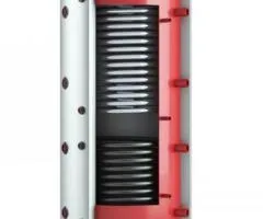
Hot water storage tank from black steel TEPLOBAK VTA-1-2000 (upper heat exchanger 5.70 m²)
143,556 ₴
Hot water storage tank from black steel TEPLOBAK VTA-1-2000 (upper heat exchanger 5.70 m²)
Київ, Україна
Buffer tank made of black steel VTA-1 is equipped with two heat exchangers. In the lower part a heat exchanger is installed, and in the upper part a stainless steel domestic hot water heat exchanger for producing hot water for household needs. The main distinction of this model is the ability to connect a large number of heat energy sources, which use both f...
Sunday
Other
вул. Стеценка, 14/44
143,556 ₴
Solar-Tech
Sunday 11:56
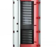
Hot water storage tank from black steel TEPLOBAK VTA-1-2000 (upper heat exchanger 4.56 m²)
131,143 ₴
Hot water storage tank from black steel TEPLOBAK VTA-1-2000 (upper heat exchanger 4.56 m²)
Київ, Україна
Buffer tank from black steel VTA-1 is equipped with two heat exchangers. A heat exchanger is installed in the lower part, and in the upper part a hot water supply system heat exchanger made of stainless steel for producing hot water for household needs. The main distinction of this model is the ability to connect a large number of heat energy sources that us...
Sunday
Other
вул. Стеценка, 14/44
131,143 ₴
Solar-Tech
Sunday 11:56
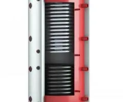
Hot water storage tank from black steel TEPLOBAK VTA-1-2000 (upper heat exchanger 3.45 m²)
119,456 ₴
Hot water storage tank from black steel TEPLOBAK VTA-1-2000 (upper heat exchanger 3.45 m²)
Київ, Україна
Buffer tank made of black steel VTA-1 is equipped with two heat exchangers. A heat exchanger is installed in the lower part, and in the upper part a stainless steel domestic hot water heat exchanger for producing hot water for household needs. The main distinguishing feature of this model is the possibility to connect a large number of heat energy sources, w...
Sunday
Other
вул. Стеценка, 14/44
119,456 ₴
Solar-Tech
Sunday 11:56
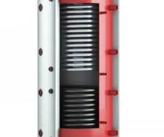
Hot water accumulator tank made of black steel TEPLOBAK VTA-1-2000 (upper heat exchanger 2.30 m²)
107,270 ₴
Hot water accumulator tank made of black steel TEPLOBAK VTA-1-2000 (upper heat exchanger 2.30 m²)
Київ, Україна
Buffer tank made of black steel VTA-1 is equipped with two heat exchangers. In the lower part a heat exchanger is installed, and in the upper part a stainless steel domestic hot water heat exchanger for producing hot water for household needs. The main distinction of this model is the ability to connect a large number of heat energy sources that use both fos...
Sunday
Other
вул. Стеценка, 14/44
107,270 ₴
Solar-Tech
Sunday 11:56
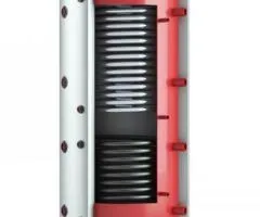
Hot water storage tank from black steel TEPLOBAK VTA-1-1500 (upper heat exchanger 5.70 m²)
132,412 ₴
Hot water storage tank from black steel TEPLOBAK VTA-1-1500 (upper heat exchanger 5.70 m²)
Київ, Україна
Buffer tank made of black steel VTA-1 is equipped with two heat exchangers. In the lower part a heat exchanger is installed, and in the upper part a stainless steel domestic hot water heat exchanger for producing hot water for household needs. The main distinguishing feature of this model is the ability to connect a large number of heat energy sources, which...
Sunday
Other
вул. Стеценка, 14/44
132,412 ₴
Solar-Tech
Sunday 11:56
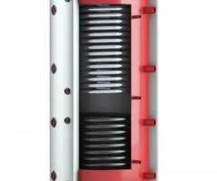
Hot water storage tank from black steel TEPLOBAK VTA-1-1500 (upper heat exchanger 4.80 m²)
121,223 ₴
Hot water storage tank from black steel TEPLOBAK VTA-1-1500 (upper heat exchanger 4.80 m²)
Київ, Україна
Buffer tank made of black steel VTA-1 is equipped with two heat exchangers. There is a heat exchanger installed in the lower part, and in the upper part a domestic hot water heat exchanger made of stainless steel for producing hot water for household needs. The main distinction of this model is the ability to connect a large number of heat energy sources, wh...
Sunday
Other
вул. Стеценка, 14/44
121,223 ₴
Solar-Tech
Sunday 11:56
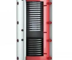
Hot water storage tank from black steel TEPLOBAK VTA-1-1500 (upper heat exchanger 3.85 sq. m.)
109,581 ₴
Hot water storage tank from black steel TEPLOBAK VTA-1-1500 (upper heat exchanger 3.85 sq. m.)
Київ, Україна
Buffer tank made of black steel VTA-1 is equipped with two heat exchangers. A heat exchanger is installed in the lower part, and in the upper part a hot water supply system heat exchanger made of stainless steel for preparing hot water for domestic needs. The main feature of this model is the ability to connect a large number of heat energy sources, which us...
Sunday
Other
вул. Стеценка, 14/44
109,581 ₴
Solar-Tech
Sunday 11:56
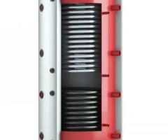
Hot water storage tank from black steel TEPLOBAK VTA-1-1500 (upper heat exchanger 2.90 sq. m.)
97,893 ₴
Hot water storage tank from black steel TEPLOBAK VTA-1-1500 (upper heat exchanger 2.90 sq. m.)
Київ, Україна
Buffer vessel made of black steel VTA-1 is equipped with two heat exchangers. In the lower part a heat exchanger is installed, and in the upper part a stainless steel domestic hot water heat exchanger for producing hot water for household needs. The main distinction of this model is the ability to connect a large number of heat energy sources, which use both...
Sunday
Other
вул. Стеценка, 14/44
97,893 ₴
Solar-Tech
Sunday 11:56
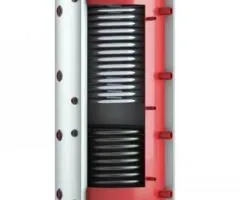
Hot water storage tank from black steel TEPLOBAK VTA-1-1500 (upper heat exchanger 1.90 m²)
85,708 ₴
Hot water storage tank from black steel TEPLOBAK VTA-1-1500 (upper heat exchanger 1.90 m²)
Київ, Україна
Buffer tank from black steel VTA-1 is equipped with two heat exchangers. A heat exchanger is installed in the lower part, and in the upper part a stainless steel domestic hot water heat exchanger for producing hot water for household needs. The main distinction of this model is the ability to connect a large number of heat energy sources, which use both foss...
Sunday
Other
вул. Стеценка, 14/44
85,708 ₴
Solar-Tech
Sunday 11:56
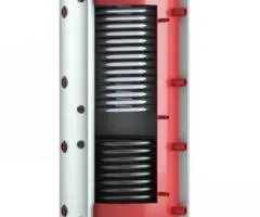
Hot water storage tank from black steel TEPLOBAK VTA-1-1000 (upper heat exchanger 4.60 m²)
107,542 ₴
Hot water storage tank from black steel TEPLOBAK VTA-1-1000 (upper heat exchanger 4.60 m²)
Київ, Україна
Buffer tank made of black steel VTA-1 is equipped with two heat exchangers. In the lower part a heat exchanger is installed, and in the upper part a stainless steel domestic hot water heat exchanger for preparing hot water for household needs. The main distinction of this model is the ability to connect a large number of heat energy sources that use both fos...
Sunday
Other
вул. Стеценка, 14/44
107,542 ₴
Solar-Tech
Sunday 11:56
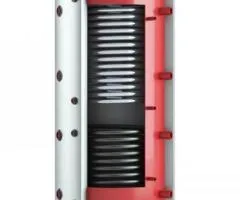
Hot water storage tank from black steel TEPLOBAK VTA-1-1000 (upper heat exchanger 3.90 m²)
99,162 ₴
Hot water storage tank from black steel TEPLOBAK VTA-1-1000 (upper heat exchanger 3.90 m²)
Київ, Україна
Buffer tank made of black steel VTA-1 is equipped with two heat exchangers. A heat exchanger is installed in the lower part, and in the upper part a hot water supply system heat exchanger made of stainless steel for producing hot water for household needs. The main distinguishing feature of this model is the ability to connect a large number of heat energy s...
Sunday
Other
вул. Стеценка, 14/44
99,162 ₴
Solar-Tech
Sunday 11:56
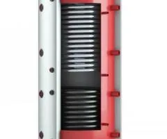
Hot water storage tank from black steel TEPLOBAK VTA-1-1000 (upper heat exchanger 3.10 sq.m.)
89,014 ₴
Hot water storage tank from black steel TEPLOBAK VTA-1-1000 (upper heat exchanger 3.10 sq.m.)
Київ, Україна
Buffer tank made of black steel VTA-1 is equipped with two heat exchangers. A heat exchanger is installed in the lower part, and in the upper part a stainless steel domestic hot water heat exchanger for preparing hot water for household needs. The main distinction of this model is the ability to connect a large number of heat energy sources that use both fos...
Sunday
Other
вул. Стеценка, 14/44
89,014 ₴
Solar-Tech
Sunday 11:56
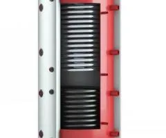
Hot water storage tank made of black steel TEPLOBAK VTA-1-1000 (upper heat exchanger 2.30 m²)
79,366 ₴
Hot water storage tank made of black steel TEPLOBAK VTA-1-1000 (upper heat exchanger 2.30 m²)
Київ, Україна
Buffer tank made of black steel VTA-1 is equipped with two heat exchangers. In the lower part a heat exchanger is installed, and in the upper part a stainless steel domestic hot water heat exchanger for preparing hot water for household needs. The main difference of this model is the ability to connect a large number of heat energy sources, which use both fo...
Sunday
Other
вул. Стеценка, 14/44
79,366 ₴
Solar-Tech
Sunday 11:55
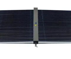
Heliosystem Altek AC-VGL-50 (For pools)
41,676 ₴
Heliosystem Altek AC-VGL-50 (For pools)
Київ, Україна
Altek AC-VGL-50 - a heliosystem based on solar vacuum collectors designed to produce hot water at a specified temperature by absorbing solar radiation, converting it into heat, storing it and delivering it to the consumer. The solar vacuum collector provides collection of solar radiation in any weather, regardless of outside temperature. The absorption coeff...
Sunday
Other
вул. Стеценка, 14/44
41,676 ₴
Solar-Tech
Sunday 11:55
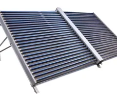
Heliosystem Altek AC-VG-50 (For large water volumes)
39,909 ₴
Heliosystem Altek AC-VG-50 (For large water volumes)
Київ, Україна
Altek AC-VG-50 - a heliosystem based on solar vacuum collectors designed to produce hot water at a specified temperature by absorbing solar radiation, converting it into heat, storing it and delivering it to the consumer. The solar vacuum collector provides collection of solar radiation in any weather, regardless of the outside temperature. The absorption co...
Sunday
Other
вул. Стеценка, 14/44
39,909 ₴
Solar-Tech
Sunday 11:55
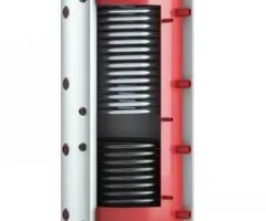
Hot water storage tank from black steel TEPLOBAK VTA-1-1000 (upper heat exchanger 1.55 m²)
69,988 ₴
Hot water storage tank from black steel TEPLOBAK VTA-1-1000 (upper heat exchanger 1.55 m²)
Київ, Україна
Buffer tank made of black steel VTA-1 is equipped with two heat exchangers. A heat exchanger is installed in the lower part, and in the upper part a stainless steel domestic hot water heat exchanger for producing hot water for household needs. The main feature of this model is the ability to connect a large number of heat energy sources, which use both fossi...
Sunday
Other
вул. Стеценка, 14/44
69,988 ₴
Solar-Tech
Sunday 11:55
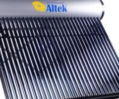
Heliosystem Altek AP-TL-30 (internal tank made of stainless steel)
32,072 ₴
Heliosystem Altek AP-TL-30 (internal tank made of stainless steel)
Київ, Україна
Altek AP-TL-30 – thermosiphon solar system from the Ukrainian brand Altek with a 300-liter tank. The inner tank is made of stainless steel SUS316L, and the outer one is made of black metal with powder coating, reinforced frame with powder coating, 5 L filler tank. The main element of this collector model is vacuum tubes made of transparent borosilicate glass...
Sunday
Other
вул. Стеценка, 14/44
32,072 ₴
Solar-Tech
Sunday 11:55
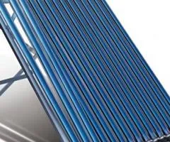
Vacuum solar collector AXIOMA energy AX-30HP24
39,230 ₴
Vacuum solar collector AXIOMA energy AX-30HP24
Київ, Україна
The vacuum collector AXIOMA AX-30HP24 is used in all-season water heating systems. This solar thermal collector is effective for year-round use in all regions of Ukraine. The vacuum tubes are coated with a three-layer high-selectivity coating ALN-AIN-SS/Cu. The solar collector is equipped with an enlarged condenser with a diameter of 24 mm, which provides a ...
Sunday
Other
вул. Стеценка, 14/44
39,230 ₴
Solar-Tech
Sunday 11:55

Vacuum Solar Collector Altek SC-LH2-30
43,443 ₴
Vacuum Solar Collector Altek SC-LH2-30
Київ, Україна
The SC-LH2 vacuum collector is used in closed-type solar systems with a pump station. The efficiency of the solar collector reaches 87-92%. Due to design features calculated for our climatic conditions, the SC-LH2 has maximum performance. It has high performance in conditions of low solar insolation, providing the collection of the sun’s energy regardless of...
Sunday
Other
вул. Стеценка, 14/44
43,443 ₴
Solar-Tech
Sunday 11:55
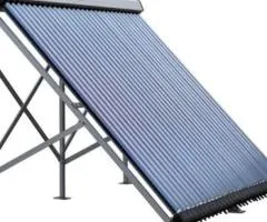
Vacuum Solar Collector Altek SC-LH1-30
39,230 ₴
Vacuum Solar Collector Altek SC-LH1-30
Київ, Україна
The vacuum collector SC-LH1 is used in closed-type solar systems with a pumping station. The efficiency of the solar collector reaches 87%. It has high performance under low solar insolation conditions, providing solar energy collection regardless of weather conditions, absorbing up to 90% of the sun's energy. The frame is made of high-quality aluminum with ...
Sunday
Other
вул. Стеценка, 14/44
39,230 ₴
Solar-Tech
Sunday 11:55
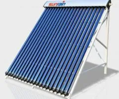
Vacuum solar collector Altek Premium (Sunrain) TZ58/1800-30R1A
64,145 ₴
Vacuum solar collector Altek Premium (Sunrain) TZ58/1800-30R1A
Київ, Україна
Vacuum tubular solar collectors Sunrain TZ58/1800-30R1A (previously sold in Ukraine under the Sunraine brand) are among the most efficient types of solar collectors. These collectors are best suited for use in moderate ambient temperatures in water supply systems where a water temperature of 50-95 ºC is required. Vacuum solar collectors have a selective abso...
Sunday
Other
вул. Стеценка, 14/44
64,145 ₴


